Designing the board.


For this week assigment, I want to do a board containing a Piezo and a LED, the objective is to blink the LED whenever the piezo sense a contact, in short, I will use the piezo as a "button" for my LED, whenever I press the button, I will also print a line on my serial monitor. I will design my board by being heavyly influenced by the "knock" arduino tutorial, in this project, the piezo is running in parallel with a 1M Ohm resistor that limits the voltage produced by the piezo and protect the pins of our attiny44. Since I didn't have any 1M omhs resistor, I will use 3 200k resistor set in series, that should do the trick.

The piezo is an analog component so we just need to connect it to an analog pin on our chip and ground the other pin. it is that easy. I will also use a 499 omhs resistor to protect my LED.


As you can see it's a pretty simple circuit, I find it fascinating to see how things that seems to me really complex at the start of the program slowly start to concretize and make more and more sense in my head. This can only be good!

Usin Eagle to design my board, we start by creating a new schem, inside the interface, we can now add our components using the add command.


once you component is selected you can then place it onto your interface and connect them togheter using the net command. You can also use the name command to connect component togheter by naming them with the same name.


Once all my components are done, here's what the schematic looks like:


You also see the 200k resistors set in parallet to the piezo but in series with each other.


This will give us a 800k resistance that should be more than enouph to reduce the voltage of our piezo.

Now that the schematics is done we can generate our board using the generate/switch to board button. We will see all our component link by a yellow line, and you have to place them on the position you want them to be using the move command.


You can now draw your route using the route command or do like me and set up your DRC tool to get ready for the Autorouter command.


Once that youre happy with your DRC parameters, you can go and select the autorouter tool, make sure you only use one layer pcb and let the magic happen!


Now that our board is done we can get it ready for the milling!

Preping the Gcode and Milling the board


To generate our toolpath, we will use Flatcam, but before even opening the program, we need to export our board as a gerber file for the traces and an excellon file for the holes. To do so, you need to go into the CAM processor tool inside EAGLE, you can load a local job for the gerber file and the excellon file.


Then just press the button process job and your good to go!

Once in Flatcam, you can open your gerber and excellon file by going into file, open gerber and excellon. once it's done it should look like that:


Now you can select your gerber job and go into the selected tab, here are my settings, I use a 0.0056" tool, and will make a 7 passes job, I combine them to fit them into one job.


you can now go back into the project tab and select the newly created .iso job. here you can prepare your cutting parameters.


You can then export this job into a Gcode file.
The drilling process is approximatively the same, just select your tool size and follow the same process.


The Gcodes are ready! let's go mill!

For the milling process make sure that your machine is correctly home and that the board is level on the machine bed, for the rest, same process as usual! I did not have my camera during the milling process, but here are the results!

Soldering the board and Programming the board


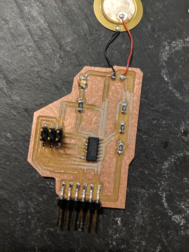
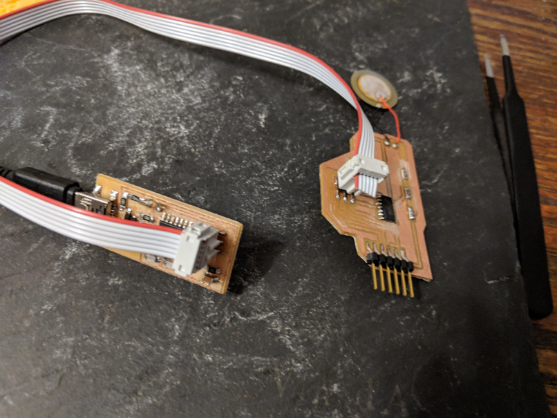
Im used to solder SMD components now, it is like a reflex, and like they say pratice makes perfect! Always be sure to be in a safe and secure environment, be relax and patient. Here is the board once everything as been done:


now that our solder are done, we are ready to program and test our board. My program is heavily influenced on the Knock Arduino exemple, it is a simple code that I modify to have a more sensible piezo and I import the Software serial library instead of the serial lbr since the attiny only runs the softwareserial. here is the final code:


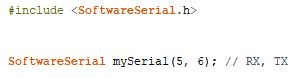
        #include <.SoftwareSerial.h>


SoftwareSerial mySerial(5, 6); // RX, TX

const int ledPin = 10;      // LED connected to digital pin 10
const int knockSensor = A0; // the piezo is connected to analog pin 0
const int threshold = 20;  // threshold value to decide when the detected sound is a knock or not


// these variables will change:
int sensorReading = 0;      // variable to store the value read from the sensor pin
int ledState = LOW;         // variable used to store the last LED status, to toggle the light
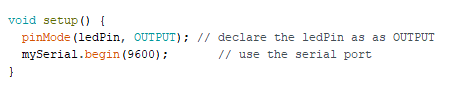
void setup() {
  pinMode(ledPin, OUTPUT); // declare the ledPin as as OUTPUT
  mySerial.begin(9600);       // use the serial port
}

void loop() {
  // read the sensor and store it in the variable sensorReading:
  sensorReading = analogRead(knockSensor);

  // if the sensor reading is greater than the threshold:
  if (sensorReading >= threshold) {
    // toggle the status of the ledPin:
    ledState = !ledState;
    // update the LED pin itself:
    digitalWrite(ledPin, ledState);
    // send the string "Knock!" back to the computer, followed by newline
    mySerial.println("Knock Knock FabAcademy!!!");
  }
  delay(100);  // delay to avoid overloading the serial port buffer
}


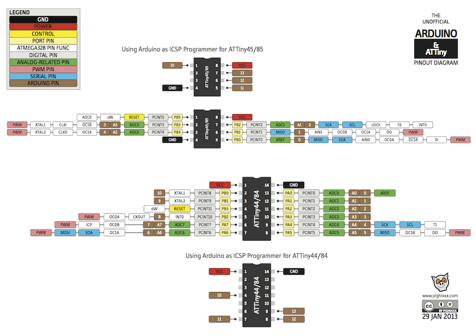
First of all we know since the beginning of our programming course that the attiny does not share the same pin number as our arduino uno, just as a reminder, here is the comparison chart for the attiny45 and 44:


Ok let's look at the code step by step, first we need to insert and set our SoftwareSerial library, we will set our RX pin as our pin number 5 and our TX pis as our pin number 6.


then we declare our variable, first, we set our led pin as the pin number 10 and the piezo on our pin analog 0. Also, we need to set our treshold in wich the piezo will send a signal.


Then we can set the variable that will change during the lecture of the code, first the variable that will store the value of our piezo and also the variable that sets the state of our LED.


In our setup, we will set ou LED as an output and we will begin our Serial.


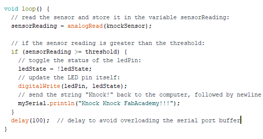
The rest of the code is our loop, it does multiple thing, it change the value of our sensorReading variable depending on the analog read of our piezo analog pin we also change our led status each time our sensorReading has a bigger value than our treshold and we print to our serial a text.


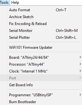
This is it, let's uplaud the code using our fabISP and see if it works!


It's not perfect but it works!! Here are my Files